TinySonar is an ultrasonic range finder based on the ATtiny13A, the ultrasonic ranging module HC-SR04 and a 7-segment display with a MAX7219 driver IC.
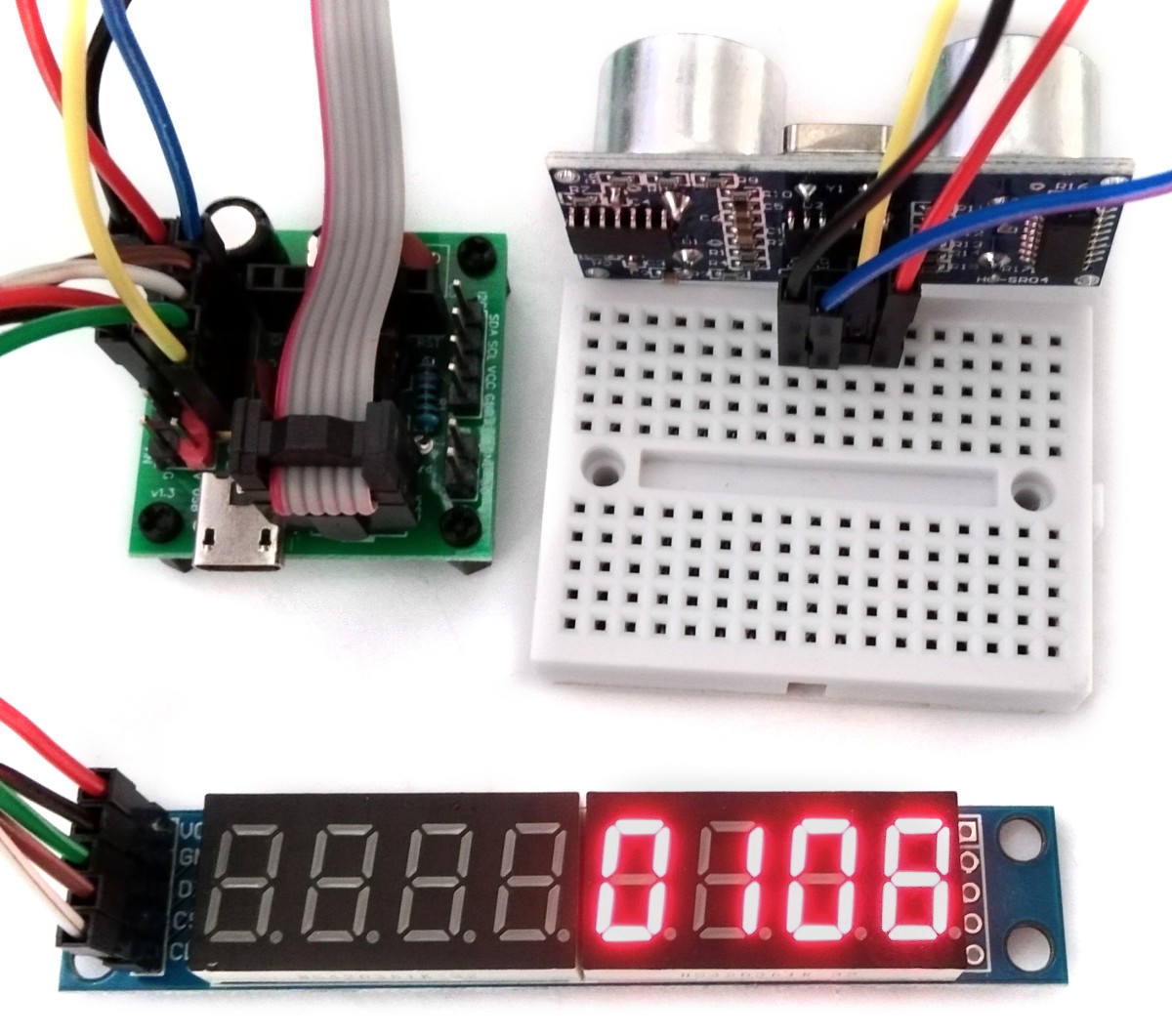
The wiring of the TinySonar is shown below:
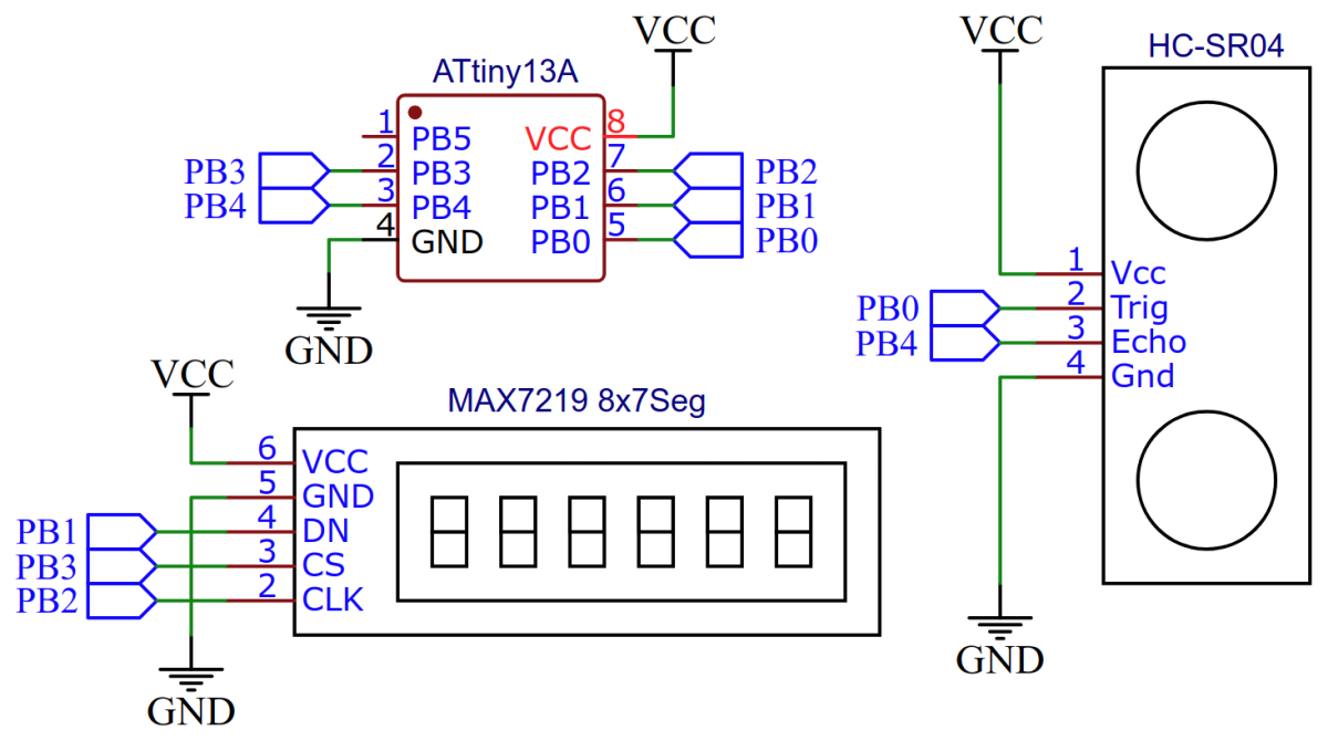
The ultrasonic ranging module HC-SR04 provides 2cm-400cm non-contact measurement function, the ranging accuracy can reach to 3mm. The module includes ultrasonic transmitter, receiver and control circuit.
The MAX7219 is a compact, serial input/output common-cathode display drivers that interface microprocessors to 7-segment numeric LED displays of up to 8 digits, bar-graph displays, or 64 individual LEDs. Included on-chip are a BCD code-B decoder, multiplex scan circuitry, segment and digit drivers, and an 8x8 static RAM that stores each digit.
This is how the HC-SR04 module is controlled:
- start measurement by applying high signal on TRIG for at least 10us,
- module automatically sends eight 40 kHz pulses and detects echos,
- module applies high signal on ECHO with the same duration as the time it took from sending ultrasonic to returning.
For measuring the duration of the ECHO signal the timer/counter0 is used with no prescaler, so it runs at MCU clock speed. Timer overflow interrupt is utilized to expand the 8-bit counter to a virtual 16-bit counter. The ECHO signal starts and stops the timer by pin change interrupt. To calculate the distance in mm from the counter value, the following approximation formula was derived:
duration[s]  = counter / F_CPU = counter / 1200000[1/s]
distance[mm] = duration * speed of sound / 2 = duration[s] * 340260[mm/s] / 2
distance[mm] = counter * 340260[mm/s] / 1200000[1/s] / 2
distance[mm] ~ counter / 7
// pin definitions
#define TRIG  PB0
#define ECHO  PB4

// global variables
volatile uint8_t  HC_done;                  // ranging complete flag
volatile uint16_t HC_counter;               // virtual 16-bit counter

// init HC-SR04
void HC_init(void) {
  DDRB  |= (1<<TRIG);                       // set TRIG pin as output
  PCMSK |= (1<<ECHO);                       // enable interrupt on ECHO pin
  TCCR0A = 0;                               // timer/counter normal mode
  TIMSK0 = (1<<TOIE0);                      // enable overflow interrupt
  sei();                                    // enable global interrupts
}

// get distance in mm from HC-SR04
uint16_t HC_ping(void) {
  HC_done = 0;                              // reset ranging complete flag
  HC_counter = 0;                           // reset counter
  TCNT0 = 0;                                // reset timer0
  GIMSK |= (1<<PCIE);                       // enable pin change interrupts
  PORTB |= (1<<TRIG);                       // send 10us trigger pulse
  _delay_us(10);
  PORTB &= ~(1<<TRIG);                      // module starts measurement now
  while(!HC_done);                          // wait for echo
  GIMSK &= ~(1<<PCIE);                      // disable pin change interrupts
  HC_counter += TCNT0;                      // calculate total 16-bit counter value
  return(HC_counter / 7);                   // calculate and return distance
}

// pin change interrupt service routine
ISR (PCINT0_vect) {
  if (PINB & (1<<ECHO)) {                   // if rising edge on ECHO pin:
    TCCR0B = (1<<CS00);                     // start the timer
  } else {                                  // if falling edge on ECHO pin:
    TCCR0B = 0;                             // stop the timer
    HC_done = 1;                            // set ranging complete flag
  }
}

// timer0 overflow interrupt service routine
ISR (TIM0_OVF_vect) {
  HC_counter += 256;                        // increment 16-bit counter by 256 on each overflow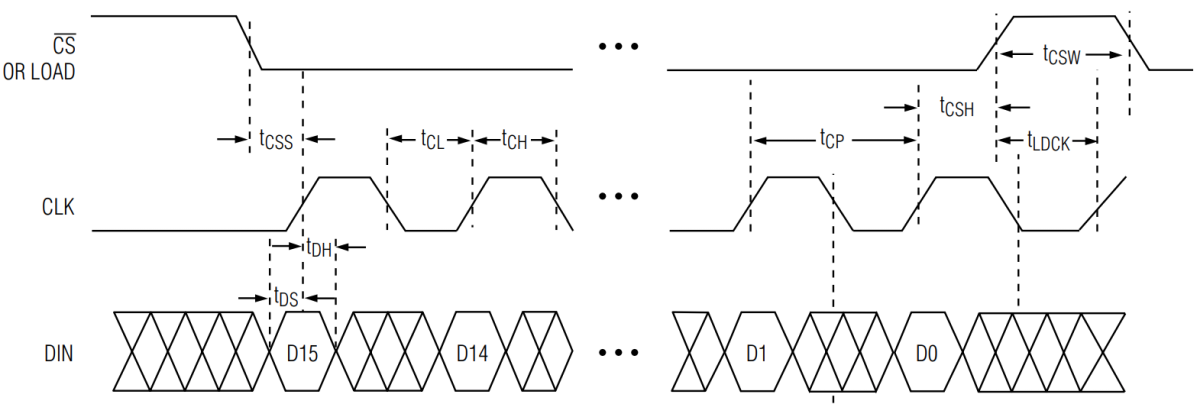
}The distance in mm is shown on a 4-digit 7-segment display which is controlled via a MAX7219 in BCD decode mode. The SPI protocol is implemented with a simple bitbanging method. The MAX7219 is fast enough to be driven without delays even at the fastest clock speed of the ATtiny13. A transmission to the MAX7219 starts with pulling the CS line LOW. Afterwards two bytes are transmitted, the register address first and the register data second. The bytes are transmitted most significant bit first by setting the DIN line HIGH for a bit "1" or LOW for a bit "0" while the CLK line is LOW. The bit is shifted out on the rising edge of the CLK line. By setting the CS line HIGH again the end of the transmission is signified, the MAX7219 latches the two received bytes and writes the data byte into the register.

// pin definitions
#define DIN   PB1
#define CLK   PB2
#define CS    PB3

// shift out byte value to MAX7219
void SEG_byte(uint8_t value) {
  for(uint8_t i=8; i; i--, value <<= 1) {   // shift out 8 bits, MSB first
    PORTB &= ~(1<<DIN);                     // clear the bit first (saves some flash this way)
    if(value & 0x80) PORTB |= (1<<DIN);     // set bit if appropriate
    PORTB |=  (1<<CLK);                     // clock high -> shift out the bit
    PORTB &= ~(1<<CLK);                     // clock low (50ns < 1000 / 1.2)
  }
}

// send command to MAX7219
void SEG_send(uint8_t reg, uint8_t data) {
  PORTB &= ~(1<<CS);                        // set CS low  -> select device
  SEG_byte(reg);                            // send address byte
  SEG_byte(data);                           // send data byte
  PORTB |= (1<<CS);                         // set CS high -> latch the bytes
}

// init MAX7219
void SEG_init(void) {
  DDRB  |= (1<<DIN) | (1<<CLK) | (1<<CS);   // set control pins as output
  PORTB |= (1<<CS);                         // pull high CS line
  SEG_send(0x09, 0x0f);                     // set BCD decode for 4 digits
  SEG_send(0x0a, 0x0f);                     // set intensity (0x00 .. 0x0f)
  SEG_send(0x0b, 0x03);                     // set scan limit at 4 digits
  SEG_send(0x0c, 0x01);                     // shutdown mode off
  SEG_send(0x0f, 0x00);                     // display test off
}

// print a number on display
void SEG_print(uint16_t number) {
  for(uint8_t i=1; i<5; i++, number /= 10) SEG_send(i, number % 10);
}The main function is pretty simple:
// main function
int main(void) {
  SEG_init();                               // setup MAX7219
  HC_init();                                // setup HC-SR04

  while(1) {
    SEG_print(HC_ping());                   // get distance and print it on display
    _delay_ms(200);                         // delay between pings
  }
}- Make sure you have installed MicroCore.
- Go to Tools -> Board -> MicroCore and select ATtiny13.
- Go to Tools and choose the following board options:
- Clock: 1.2 MHz internal osc.
- BOD: BOD 2.7V
- Timing: Micros disabled
- Connect your programmer to your PC and to the ATtiny.
- Go to Tools -> Programmer and select your ISP programmer (e.g. USBasp).
- Go to Tools -> Burn Bootloader to burn the fuses.
- Open TinySonar.ino and click Upload.
- Make sure you have installed avrdude.
- Connect your programmer to your PC and to the ATtiny.
- Open a terminal.
- Navigate to the folder with the hex-file.
- Execute the following command (if necessary replace "usbasp" with the programmer you use):
avrdude -c usbasp -p t13 -U lfuse:w:0x2a:m -U hfuse:w:0xfb:m -U flash:w:main.hex
- Make sure you have installed avr-gcc toolchain and avrdude.
- Connect your programmer to your PC and to the ATtiny.
- Open the makefile and change the programmer if you are not using usbasp.
- Open a terminal.
- Navigate to the folder with the makefile and main.c.
- Run "make install" to compile, burn the fuses and upload the firmware.