This is a beginners guide to motor position control using the ODrive motor controller meant to be a great first-read.
ODrive has its own great documentation page and getting started guide, but I found it easy to get lost in the plethora of information as a beginner.
Based from my experiences and struggles, I was inspired to create a guide meant for users who have zero experience with ODrive and encoders in general. The guide goes into detail on how set-up the ODrive board, how to interface it with an encoder through ABI, and how to tune the control loop.
- Prerequisites
- Recommended resources
- Materials
- Setting up the testbed (optional)
- Wiring the encoder using ABI
- Preparing the motor
- Which operating system to use
- Updating the ODrive firmware
- Configuring the ODrive
- Tuning
- What's next
No prerequisite knowledge is assumed. The guide will walk through every single detail needed to set-up positional control for a brushless motor. However, as it is a beginners guide, it is not comprehensive, so I highly encourage taking a look at the recommended resources to gain more familiarity with how everything works.
ODrive Getting Started - This guide is only meant to be an introductory guide and is not meant to replace the full, comprehensive ODrive documentation. This getting started page from ODrive, as well as other pages in the docs, is the best resource for the ODrive user.
It is a good idea to also look over the datasheet of your encoder. Shown below are resources for the AS5047 encoder:
AS5047 Eval Board Manual - AS5047P evaluation board manual. Great for getting familiar with its usage.
AS5x47y Interfaces - Documentation on the communication interfaces of the AS5x47 encoder family. Good for understanding how to connect the AS5047 encoder with the ODrive.
- ODrive motor controller
- Comes with a 50W power resistor. This guide will assume the 24V variant.
- Encoder
- In this guide, any ABI capable encoder would do. The ODrive does provide support for other interfaces, but we would use ABI here. The one used is the ASM AS5047P magnetic rotary sensor evaluation board.
- Brushless motor
- Any 12-24V BLDC motor would work as long as it does not exceed the ODrive peak current capability. For this guide, a small motor would be recommended. The one used is a Sunnysky V3508 580KV.
- Power supply
- Any 12-24V DC power supply or lipo battery that can supply the current needed for the motor.
- Soldering iron
- Male to female jumper cables
- Epoxy
- Any adhesive to attach the magnet to the motor's shaft would do.
For the optional testbed frame:
- 3D printer
- M2.5 screws and nuts
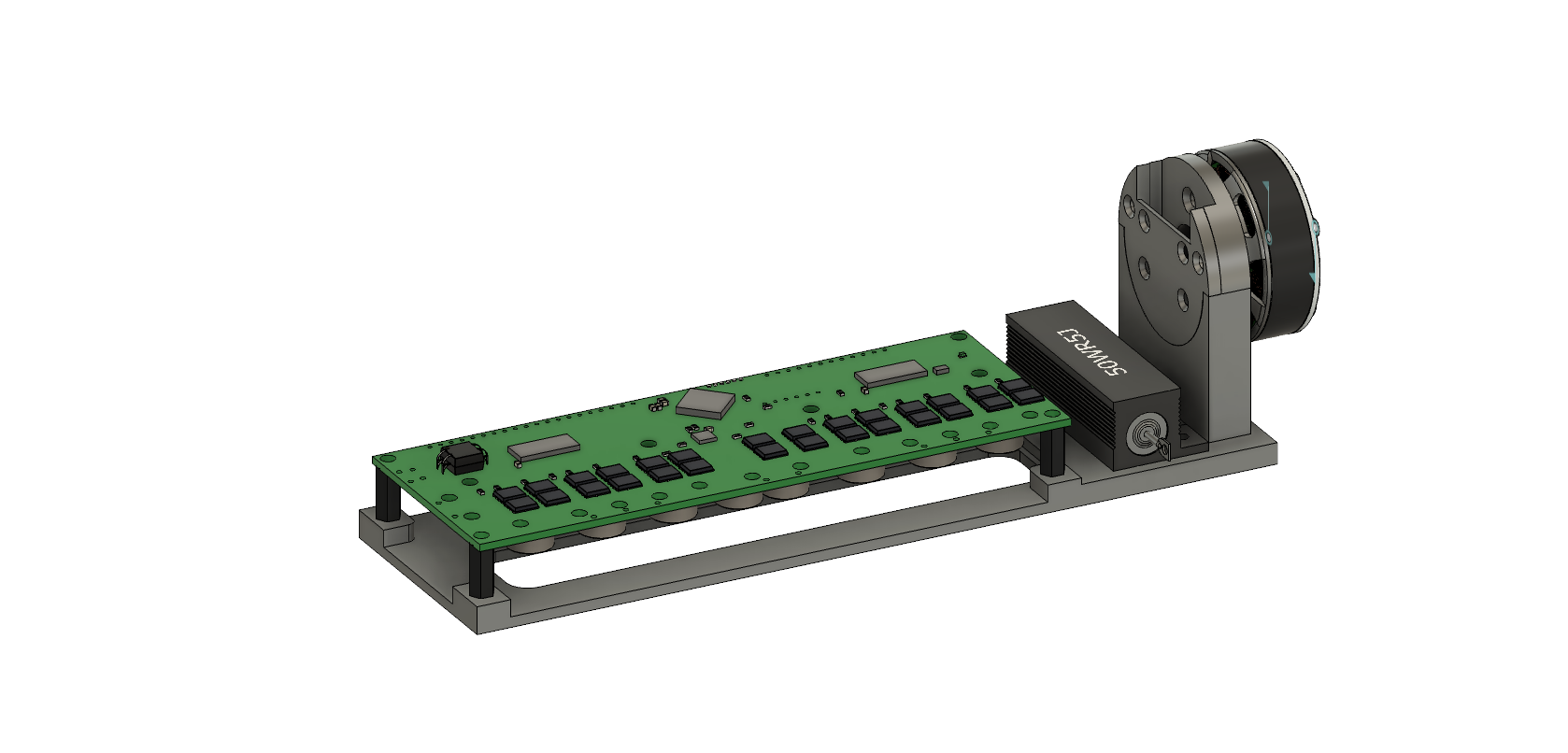
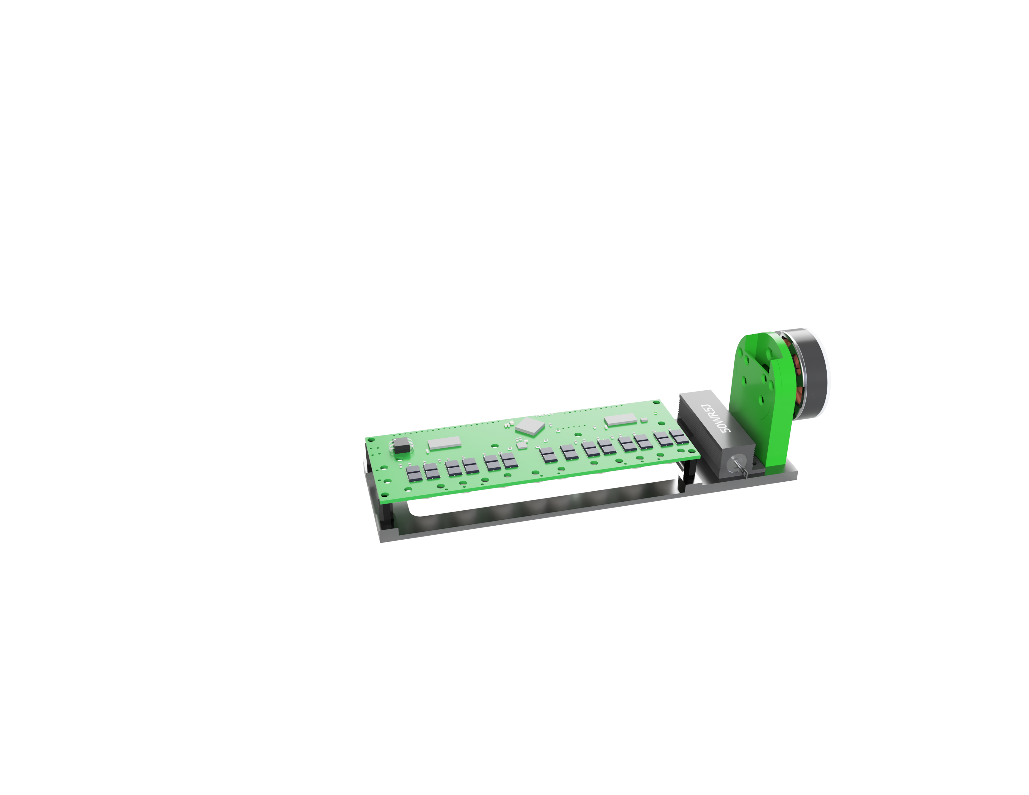
To make it easier to use the ODrive while testing it with the motor, I designed a 3D printed frame to hold the ODrive and the power resistor, as well as have space to mount the motor and encoder. The STL file for the design is available in the designs folder.
The frame was printed at 20% infill. Adjust this infill, the screw hole sizes, and the motor mounting holes to match your own set-up. The motor mount is specifically designed for the Sunnysky V3508 brushless motor. The actual Fusion 360 file is available to edit the design.
The ODrive attaches via the included standoffs in the kit and regular M3 nuts. The included power resistor also attaches to the frame using regular M3 screws.
To accomodate your own motor, design the motor mount, and simply adjust the holes in the testbed frame to match the screw holes on your mount. Note when designing the motor mount that the distance of the magnet from the encoder is specified in the datasheet.
This portion shows the AS5047P magnetic position sensor, but the instructions generalize for any ABI capable encoder.
For this guide, ABI was chosen over SPI since it is easy to get started with and straightforward to expand to two encoders. Each motor terminal also has its own set of terminals needed for ABI. If you prefer another interface such as SPI, you could look over the ODrive encoder page for guidance on that.
The index signal of the encoder is then used to avoid having to calibrate everytime the ODrive starts up. This is one advantage of absolute position encoders.
To prepare the AS5047P evaluation board, first solder the included header pins. Then, short the correct pins for either 5V or 3.3V usage. Note which one you selected, as this would be important later on when connecting to the ODrive.
I shorted mine by soldering the pads together to keep the form factor thin, but the encoder also comes with a jumper device that plugs onto the presoldered header.
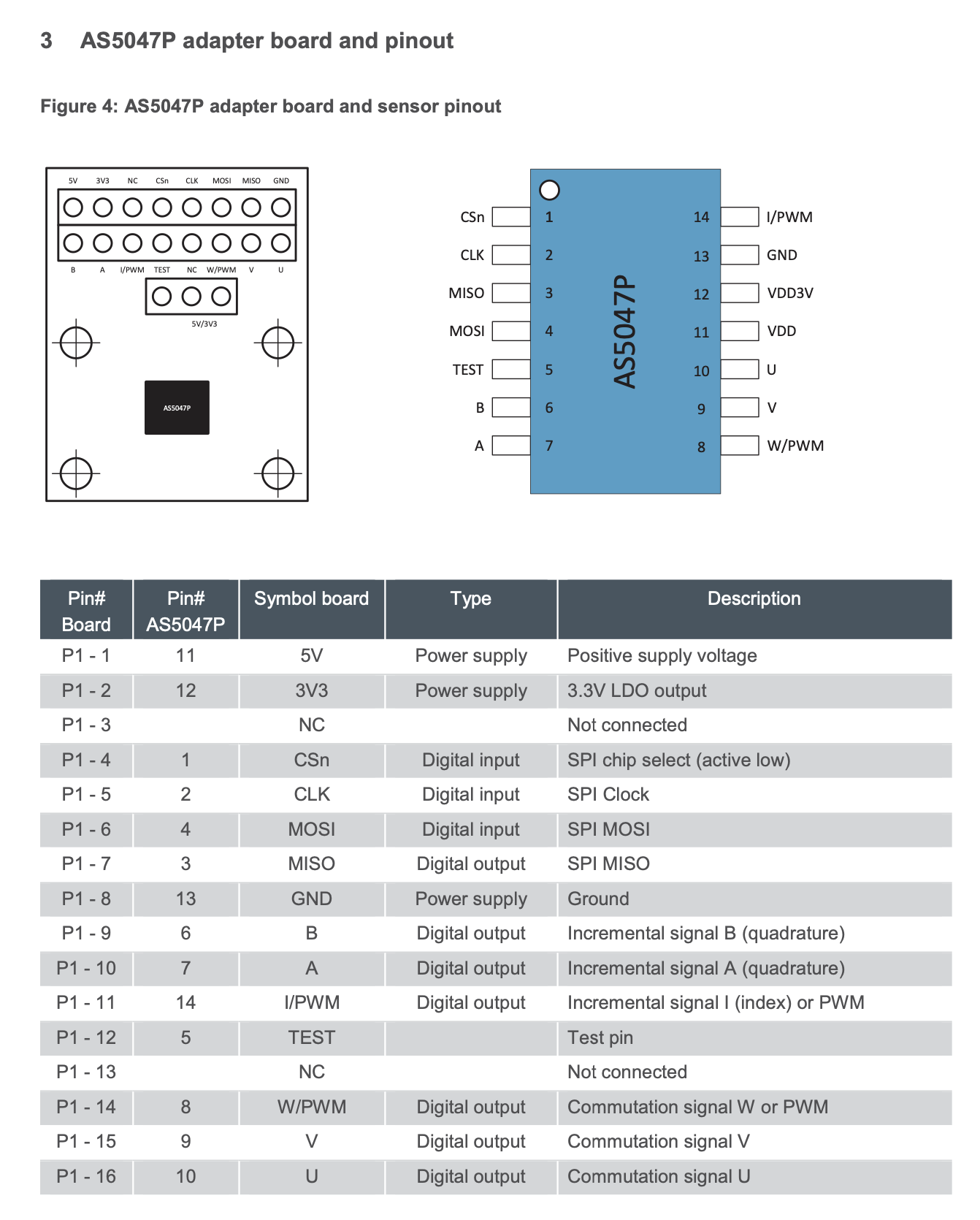
Now, we can examine the pins on the AS5047 evaluation board. This portion of the datasheet nicely summarizes everything we need to know:
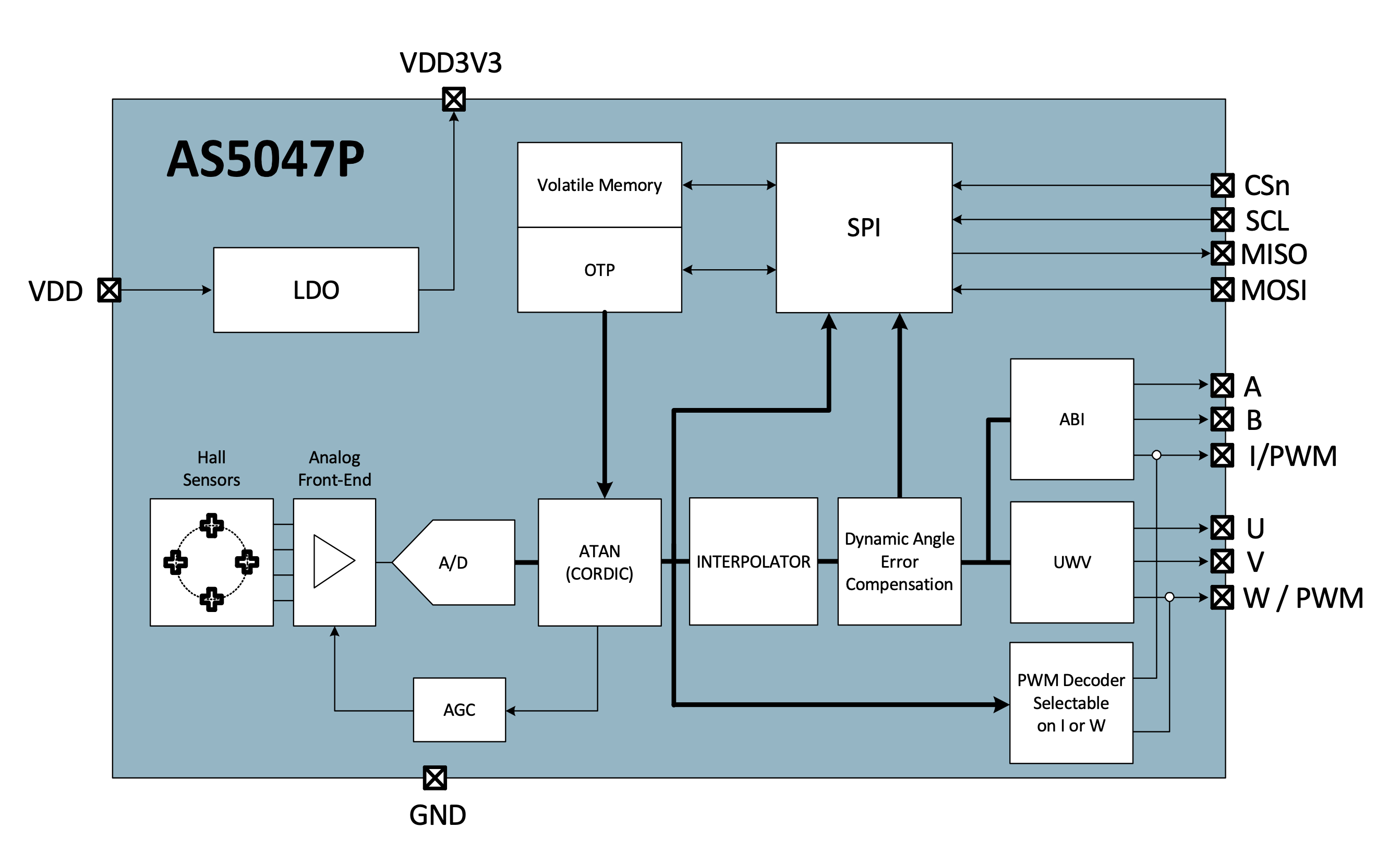
This portion of the datsheet nicely shows what we need for ABI (and other interfaces like SPI should you prefer those):
On the ODrive board, there are pins marked A, B, Z, 5V, and GND for each motor. Since we are using motor 0, we use the pins close to M0. A, B, GND, and 5V (or 3.3, depending on what voltage was selected earlier) all go to the corresponding pins of the same name on the AS5047 board. The Z pin then goes to the I (index) pin of the AS5047 board.
The wiring scheme for ABI, from ODrive --> encoder, would therefore require 5 wires and are:
- A --> A
- B --> B
- Z --> I
- 5V --> 5V
- GND --> GND
The magnet has to be attached to the shaft of the motor, which sounds easier than it actually is. The magnet does not snap on the shaft perfectly down the center and snaps around to other portions of the shaft easily. While positioning the magnet onto the shaft, you would feel the center position. Be careful as a slight nudge in any direction caused the magnet to snap to an off-center position.
I found that using a 2-part epoxy worked well in holding the magnet in place even while it was still curing. Some people use a jig to precisely center the magnet and hold it in place while the adhesive set, but I felt it was not needed as the epoxy was strong enough to hold it and easy enough to eyeball the center.
This diagram from the ODrive documentation provides a great overview of how everything connects together:
The power supply is wired directly to the terminals on the short side marked DC.
The three cables from the motor go to the three terminals on the long side. Choose either of the three-phase terminals, which are either for motor 0 (M0) or motor 1 (M1). Note which one you chose, as this will be which axis you would be using for commands later on.
We would also need to wire the included power resistor (or your own, if you have calculated a specific value that you need) to the ODrive. If you are using a battery as the power supply, not wiring it wouldn't be a problem since the ODrive would just feed power back to the battery and recharge it. However, problems could arise if a power supply is used. The ODrive documentation details this problem more in-depth.
I highly recommend using a Windows or Linux device. If you prefer macOS, I recommend updating the firmware and tuning using a non-Mac device. After this, everything else can be done on a Mac.
First, it is a good idea to update the ODrive firmware to the latest one. The board most likely comes shipped with the latest firmware, but it is good to know how to update it in the future.
It might be as easy as following the steps outlined at ODrive Tool, but a lot of errors could also go your way.
I tried this instructions on both Windows and macOS. The Windows instruction worked smoothly, but the macOS did not, which is why I recommend not using a Mac for this potion.
On the Mac, running the command odrivetool dfu should have done it, but for me it got stuck at putting the device into DFU mode.
$ odrivetool dfu
Putting device into DFU mode...
Switching the DIP switch into DFU mode on the board makes no difference either.
Since the python DFU tool doesn't work, we can instead convert the binary file through the ARM development tools, and flash the firmware using dfu-util.
Note that previously we could install gcc-arm-embedded using
brew cask install gcc-arm-embeddedbut this no longer works after ARM depreciated the use of PPA.
To get around this fact that gcc-arm-embedded is no longer on homebrew, we can instead tap into osx-cross/arm and install from there.
brew tap osx-cross/arm
brew install arm-gcc-bin
At the moment I did this, macOS Big Sur still has issues, and you may run into CLT not supported errors. To get around this, simply download and update the Command Line Tools for Xcode at Apple's website.
Finally, after all this, we can finally follow the second step on the macOS portion of the ODrive Tool page, replacing the filenames with the correct ones when needed.
Now, follow the ODrive getting started page starting on the "Downloading and Installing Tools" portion for your operating system. It does a great job of explaining everything and I found it to be extremely helpful and beginner friendly, so there is no need to rewrite another guide for that portion.
Some useful things to note while doing the getting started guide:
- For the Sunnysky V3508 motors used
- I set the maximum calibration current to 5A, but you should select any current you are comfortable with (the default is 10A).
- I left vel_limit to its default value.
- The motor has 14 magnets in the rotor, so pole_pairs should be set to 7. An easy way to find this is to simply count the number of magnets (if visible) of the motor and divide it by 2.
- The motor is rated at 580KV, so torque_constant should be set to 0.01425862069. With earlier firmware versions, you might get the error "attribute not found", which is why we updated it.
- The motor is a hobby brushless motor, so set motor_mode to MOTOR_TYPE_HIGH_CURRENT.
- For the AS5047 encoder used
- Count per revolution is 4000, so set cpr to 4000. Note that while the data sheet says the default is 4096, I observed the actual value to be different after much testing and frustration. Other users on the ODrive forum seems to have the same problem too.
After finishing the getting started guide, everything should be set-up and ready for tuning.
For this part, I highly recommend using Windows or Linux over macOS, since the liveplotter tool currenly crashes on macOS. Without it, it is extremely difficult, if not impossible, to properly tune the controller.
The tuning guide on the ODrive docs is quite unfriendly to the first time user. However, it is still worth a read before following this guide to see where the overall procedure came from.
Before starting the tuning process, make sure that the axis state is in closed loop control mode.
<odrv>.<axis>.requested_state = AXIS_STATE_CLOSED_LOOP_CONTROLNote that <odrv> is replaced with the odrv number (0 for the first ODrive plugged into the PC) and <axis> is replaced with the axis number you chose earlier (0 for motor 0 and 1 for motor 1). For example, when setting up M0 and for a single ODrive board plugged in:
odrv0.axis0.requested_state = AXIS_STATE_CLOSED_LOOP_CONTROLTo return to the idle state at any point, we can set the state to AXIS_STATE_IDLE.
<odrv>.<axis>.requested_state = AXIS_STATE_IDLEThe liveplotter tool is used to dial in the gain values. To graph the position setpoint against the measured position:
start_liveplotter(lambda:[odrv0.axis0.encoder.pos_estimate, odrv0.axis0.controller.pos_setpoint])You can read more about the liveplotter tool here.
Finally, when anything goes wrong, the state goes back to idle or undefined and the whole thing stops. Follow the procedure as described in the getting started guide, which is redescribed here for convenience:
Read the errors by
dump_errors(odrv0)then figure out what is causing it from the error code documentation.
After addressing the issue, clear the error slate.
dump_errors(odrv0, True)Now, begin the tuning process by setting all the gain values to zero.
<odrv>.<axis>.controller.config.pos_gain = 0
<odrv>.<axis>.controller.config.vel_gain = 0
<odrv>.<axis>.controller.config.vel_integrator_gain = 0
Increase vel_gain by around 30% per iteration until the motor exhibits some vibration. The vibrations are noticable and make a distinct reverberating noise.
To trigger vibrations, we could use input_pos with the command
<odrv>.<axis>.controller.input_pos = <Float>where Float is in turns and could be 1 turn, 1.5 turns etc.
For smaller motors, we could also disturb it slighly by hand but for larger motors, it might not be possible and/or safe.
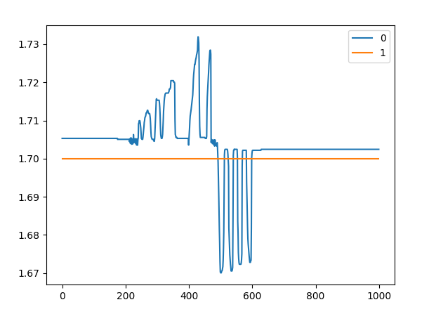
While increasing vel_gain, we can easily see through liveplotter when some vibration is occuring:
If vel_gain is excessively high, the motor could vibrate even without any disturbance.
Sometimes, the motor spins too quickly and causes the whole thing to stop. Read and clear the errors as described above, then increase vel_limit.
At the point where the motor exhibits some vibration, decrease vel_gain to half of its vibrating value.
Now, increase pos_gain by 30% per iteration until you see overshoot.
To see if the controller overshoots, you could send a new input_pos input position again and view the liveplotter graph. Alternatively, for smaller motors you you could turn the motor by hand and let go, then view the liveplotter graph.
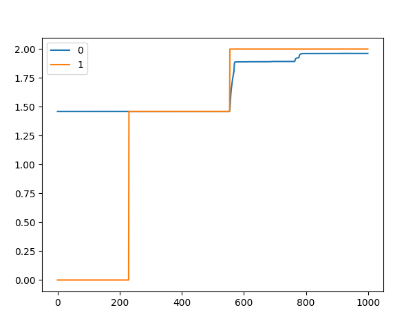
For example, setting input_pos equal to 2 generates this graph on liveplotter:
It is clear in this case that undershoot is present, so we need to increase pos_gain until overshoot occurs. Increasing pos_gain by 30% per iteration and disturbing the motor by hand yields this graph in liveplotter, where we see overshoot starts to occur.
At the point where overshoot occurs, back down pos_gain until the overshoot disappears.
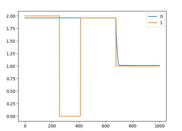
Getting rid of the overshoot and sending another input_pos command generates this graph on liveplotter:
Now, we can set vel_integrator_gain using the formula 0.5 * bandwidth * vel_gain.
From the ODrive docs:
Bandwidth is the overall resulting tracking bandwidth of your system. Say your tuning made it track commands with a settling time of 100ms (the time from when the setpoint changes to when the system arrives at the new setpoint); this means the bandwidth was 1/(100ms) = 1/(0.1s) = 10hz. In this case you should set the vel_integrator_gain = 0.5 * 10 * vel_gain.
Thus, to find the bandwidth value, set a new input_pos and view the time it takes to settle into the set position using the liveplotter graph.
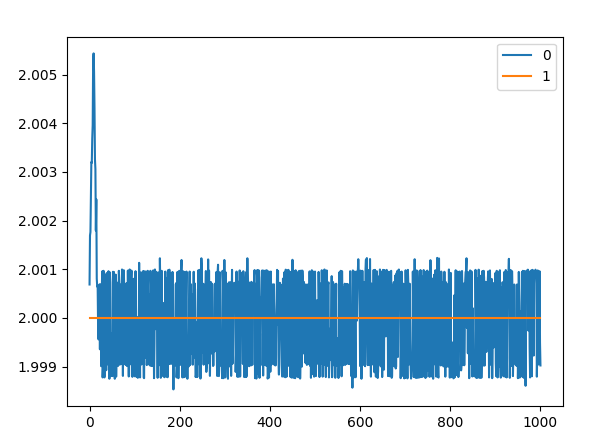
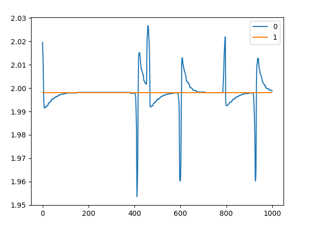
After setting vel_integrator_gain, disturbing the control loop by manually turning the motor yields this liveplotter graph:
After this, congratulations! The control loop should now be tuned.
At this point, everything should be set-up and ready to go.
I recommend looking over the ODrive documentation for a comprehensive tour of its capabilities.
Have fun working on your projects!
