DISCLAIMER: This is sort of a blog where we show what we did in the time between 2020 and 2021. It is not a full project nor a specific application development. We are only sharing interesting stuff we studied and what troubles we faced while doing so.
In this repository you will find example codes and tests codes we have developed.
- IR Remote Controller
- Temperature
- Arduino power consumption
- WiFi and local server connection
- Displaying results on a website
- Connecting ESP8266 to the internet
- Going beyond with the website
- Improvements to the ESP8266 algorithm
- MQTT
- Hardware design
- Future modifications
Firstly, we wanted to turn on and off an air conditioner. We investigated ir protocols to learn about them and to know which where the most widespread among home appliances. Soon we discover there are several different protocols and testing with Arudino module based on the VS1838 sensor and a TV remote control we realized that the NEC protocol is the most common one.
However, AC's don't work like this. Instead, they use a way longer protocol which we could not find its name.
Here we encounter two problems:
- The library we were using (Arduino-IRremote) had a reciever buffer limit of 100 "symbols" (we will talk about what the "symbols" are in a minute).
- The AC (and here we mention that there are a lot of AC's that behave similarly) had a much longer message and didn't belong to any ir protocol we studied so far.
Both problems are related, in the way that with the help of an osciloscope we saw the message transmitted by the AC's remote and didn't fully fited to the protocols we studied and when we tried to capture the raw "symbols" recieved and send them to the AC, it wouldn't respond. So making a new research and further investigating the libraries recomendations we discovered that AC's do not comply with standard ir protocols. To solve this problem first we downloaded the code provided here and printed the lenght of the array. We realized that it had 227 "symbols" and that the "symbols" represented the time in microseconds between two edges for a PWM signal with a carrier frecuency of 38[kHZ].
Now there was a new challenge. The variables captured during the loop of the Arduino code were saved in the SRAM memory and soon we ran out of available memory and the program crashed. The apparent solution was pre-recording the on and off codes and save them as global variables.
Going a bit further, we discovered that there is a way to save variables (globals and/or static only) in the Flash memory by using the PROGMEM function.
Now we managed not only to turn on and off the AC but also there is the posibility to save future codes to gain more control over the appliance.
We had the DHT11 sensor lying around and played with a couple lines of code to see how it worked. Not surprisingly it worked just fine and we didn't have much trouble at all.
The only important thing to bare in mind is that the DHT11 is a digital sensor and needs to have a "settling time" between two consecutives reads (5 seconds aproximately).
We follow this tutorial as a guide.
We devoted some time to investigate how to make the Arduino consume less current than the regular 20-70 [mA] (we measure that current in idle mode and the measurments correspond to Arduino Uno and Mega with ATMega2560 respectively).
We measure the current consumption using a multimeter in series with the power source. The wires were connected trhough one board to the 5V and GND pins of the board being measured in order to conect the multimeter properly.
The first thing we noticed was that using the Vin pin rather than the 5V pin inmediately brought down the current from 20 [mA] to 12 [mA] as explained in this video. Afterward we use the clock divider in CLKPR register to slow down the clock. We saw significant changes in current consumption when the clock was up to 4 [MHz], with slower clocks our measurements did not show significant changes (it remained near 5 [mA]).
Finally we investigated about the LowPower library. It worked pretty well and the powerDown method brought the board's current down from 20 [mA] to roughly 6 [mA] (using the 16 [MHz] clock). However we did not see significant changes using this library while having a slower clock.
To conclude, both methods are useful in a variety of applications where the board is powered using a battery.
NOTE: We didn't desolder the always-on LED that shows the board is ON, by doing this you could bring down power consumption by a couple of mA (see the video linked before for more information). Also the voltage was 5 [V] the whole time, you also can use less input voltage to drop the current consumption.
Soon we realized that it would be interesting if the data from the sensors could be stored in a database.
To achive this, we studied a bit of MySQL and got familiarized with XAMPP and PHPMyAdmin, a GUI to quiclky deploy a database with all the information we needed
Furthermore, we learned some php, javascript and HTML to develop a way to comunicate with the database and to display the information in a graph (we intend to use the templates available at highcharts).
We followed the tutorials from Ioticos that explain how to use XAMPP and PHPMyAdmin, how to record data into the database from an ESP8266 and how to display the information.
Ultimately we expected to showcase different graphs and images in an organized and nice-looking website. We had to learn how to upload our local server to an interntet hosting service. For this we decided to go with 000webhost beacause it provided website and database hosting services.
You can check our site. It only displays an illustrative graph of what we expect to have in the future with the Arduino sensors information. The template of the site you can find it in colorlib (also uploaded as .zip in the ./Pagina_web/ directory. We used the AdminLTE 3.
Recently we managed to fetch information from the DB thanks to the ioticos and ELECTRONOOBS tutorials and materials.
The result is prety satisfactory. You can check out the files in the ./Pagina_web/ directory of this repository.
NOTE: Please notice that in order to work, the relative paths of the files and the names must match the files locations inside the page directory.
The last fundamental step to set the sensors to log information to the database via WiFi, is to connect the ESP8266 microcontroller to the house WiFi network.
The board we used is the Nodemcu Wifi Esp8266 Lua.
After reading the documentation of the ESP8266 Arduino Core we knew that the microcontroller had two working modes:
- Soft Access Point.
- Station.
We decided that in order to get the most out of the ESP8266, first it had to initiate it in AP mode and list all the networks available so the user can choose to which connect from. After that, the microcontroller enters in station mode and then statrts sensing temperature and humidity data and sending it to the database. We inspired our code in this tutorial.
A useful function we implemented is that the microcontroller saves in its EEPROM the SSID and password of the last connected network. This is useful for example if the power goes of, when it's turn on again the device tries to connect to the network without needing the user to configure it again.
All the user configuration (selecting the correct network (SSID) and introducing the network password) is done with the user connecting to the device's network (while in AP mode) and enterning to a specific site (determined by the local IP adress saved in the microcontroller code, in this case is: 192.168.4.22) that shows all the availble information.
In order to make a more professional website, we decided to implement a user managment system. The users now only have access to the index page without logging in. If the user wants to visit the other pages it has to either log in or register as a new user. The system is a bit rudimentary for the moment but we are looking forward adding more and better features (as for example logging in with G+ or Facebook).
Also, we added different pages where the user can check a daily evolution of the temperature and humidity, a monthly evolution or a historic evolution of the variables. In the last page we developed so far, the user can request an evolution report of the variables between two dates he defines.
We tried to optimize the software using interrupts, a statistical approach to the data collected and improving some new features.
The first thing we did was upgrading the user interface so the device can be disconnected from the internet via a web page with a disconnect button.
Secondly, we did not like the deviation that temperature and humidity sensed values had. To solve it, we decided to collect 20 values, calculate the average and then uploading them to the database. This helps to upload less values to the database (saving not only space in the DB but also bandwith due to less HTTP requests).
In the third place, we included four buttons so the user can manually change the state of the relays. This is useful if the device disconnects from the internet and can't read the DB anymore.
Finally, we researched how to use timer interrupts. We did not find very useful documentation, but used the example codes of this repository to find out how they work. However, many people had trouble while using timer interrupts and WiFi connectiom (sometimes the board crashes or disconnects and never re-connect again). We experienced the first problem, the board enter in panic mode and printed some message error in the terminal. We suspected that te reason this happened, is because the Interrupt Service Routine (ISR) exceeded the Watchdog Timer (WDT) and made the microcontroller crash. The first solution we tried, was adding the yield() function (similar to delay(0) or delay()) in the ISR, but it kept crashing (we added several yield() in many other parts of the code and resulted in the same error). The second solution, was creating a special ISR, that the only thing it did was toggling a flag, that was used in a conditional in the main loop function to excecute the former ISR function. This solved the problem temporarily, however we did not let the microcontroller run for several hours. We are not satisfied with the solution and we are looking forward finding a better way to deal with it.
The WiFi connection uses the ESP8266 timer 0, so there is only one timer to freely use (timer 1). We will try our best to implement the sensing function with timer1. However, we feel confindent about the Tickers library as explained here to deal with "interrupts" in the future or in situations when you have more than one callback function.
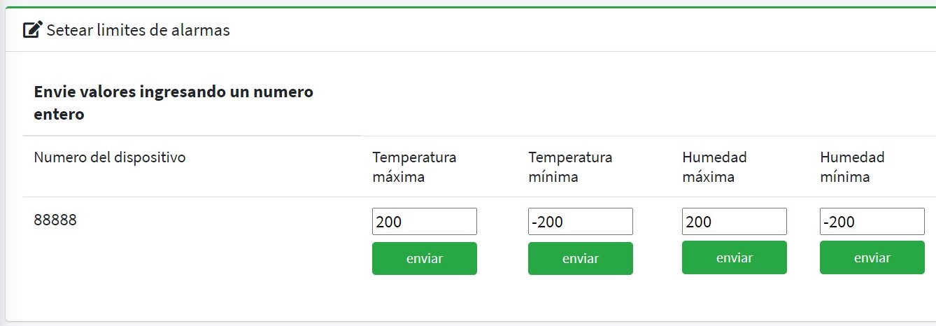
In the latest update we added an alarm function. The user can send values for maximun/minimun temperature or humidity to be checked by the microcontroller. If the threshold is exceeded an email is sent to the user to let him know. In the mail there is information about what thershold has been exceeded and which device has sent the alarm. Here is a screenshot from the webpage:
We worked all this time using HTTP requests to comunicate to the online DB. Doing further research, we found out that the most wide spreaded way of connecting many devices with the internet was MQTT. The protocol basically requires three elements a publisher to a topic, a broker and a subscriber to that topic. Nontheless, there was a lot of information to assimilate and took us a while to understand what challenges we were facing. Our first step was to follow SinapTec tutorials in order to understand how it worked and to get used to the new tools that are needed. In conclusion, we are certain that MQTT is the ultimate protocol to implement in a microcontroller due to its several advantages in speed and portability.
When the MQTT protocol was implemented, we experimented several issues (the microcontroller crashed every now and then). We figured out that was due to the buttons connected to the D3, D4 and D8 pins. The logic was only correct for the D8 pin, because it has a pull down internal resistor (D3 and D4 have both internal pull up resistors). To solve the problem we intverted the physical logic of the buttons connected to D3 and D4 (they are now buttons with pull up resistors).

The angular stone of the network is a Python script. This script is suscribed to every topic and is responsible of comunicating with the microcontroller, the database and the webpage. It handles all the DB queries (updates, requests, etc...) and publishes the requested information in specific topics.
To enhance the project and make a real device, we decided to design the PCB (Printed Circuit Board). We design it in a way that the microcontroller can be taken away for other projects, to give the user an extra level of freedom.
This is the electrical diagram:

This is the routing of the circuit in the PCB:

And finally here is the 3D model, we are looking forward to sending a few pieces into production so we can build some prototypes:

We are always thinking in whats next. In the issues section you can watch what we are planning to do next in the various parts of the project.